Release time: 2026-08-21

Custom LED Lens Design for Enhanced Optical Efficiency
Lighting systems fail when light goes where it should not. Standard lenses waste up to 30% of emitted lumens through scattering and poor beam control. Custom LED lens design solves this problem by tailoring refraction, reflection, and distribution to exact application needs.
Why does optical efficiency matter so much? Higher efficiency means lower power consumption, reduced heat generation, and longer LED lifespan. In automotive lighting, industrial fixtures, or architectural installations, every lost photon adds cost. A well-designed custom LED lens can push system efficiency from 85% to 95% or higher. Let me give you an example from our 2025 case work: a client in the agricultural sector needed uniform light spread across 2,400 square meters of greenhouse shelving. Off-the-shelf optics delivered 78% uniformity at best. After redesigning the led lens with freeform surfaces, uniformity jumped to 94%.
Fundamentals of LED Lens Optics
Light extraction depends on the refractive index differential between the LED die, encapsulant, and lens material. Silicone lenses with 1.41 refractive index outperform PMMA (1.49) in total internal reflection scenarios. Total internal reflection (TIR) lenses, one specific type of optical lens, capture side-emitted light that standard domes miss. They achieve beam angles from 5° to 60° with minimal spill. The trade-off, however, is increased lens height and material volume. Fresnel lenses provide a compact alternative but introduce internal facet losses of 8-12% (Chen et al., 2023, Journal of Photonics). Meanwhile, compound parabolic concentrators (CPC) offer excellent collimation for collimator lens applications but perform poorly with wide-angle emitters.
Key Factors in Custom Lens Geometry
The emitter shape—whether square, round, or rectangular—dictates the lens entry surface. A rectangular die (common in high-power LEDs) creates elliptical light patterns with spherical lenses. Therefore, our team uses toric surfaces or anamorphic optics to match emission patterns precisely. Surface finish also plays a role. Polished surfaces maximize clarity, while textured surfaces scatter light for uniform illumination. We measure efficiency with integrating spheres and goniophotometers, comparing total flux output against baseline values.
Problem: The Seven Deadly Sins of Standard LED Lenses
Standard lenses suffer from predictable failures. Spherical aberration causes color fringing at beam edges. Chromatic dispersion separates wavelengths unequally. Fresnel losses at air-lens interfaces reduce transmittance by 4% per surface. Additionally, uneven irradiance creates hotspot centers with dark annular rings. Beam divergence drifts with temperature fluctuations. Material yellowing under UV exposure dims output over time. Finally, mounting misalignment—even at 0.5mm—drops efficiency by 15%.
Why Off-the-Shelf Solutions Often Disappoint
Generic lenses assume a point-source emitter, but actual LEDs have finite dimensions. A 3x3mm die cannot behave like a pinpoint. The result? Blurred beam edges and inaccurate projection angles. In automotive headlamps, this creates dangerous glare for oncoming traffic. In street lighting, it means dark zones between poles. Standard lenses also ignore the secondary optics of reflectors already in place. Therefore, custom design integrates the full optical path, not just the lens element.
Solution: Step-by-Step Guide to Custom LED Lens Design
Our process follows five concrete stages. Follow them in order to avoid costly rework.
- Define optical specifications — measure the LED's real emission profile using a far-field goniophotometer. Capture luminous intensity distribution at 1° intervals. Set target beam angle, illuminance level, and uniformity ratio (typically 0.7 minimum).
- Select material and process — choose between PMMA (cost-effective, up to 90°C), polycarbonate (impact-resistant, up to 130°C), or silicone (flexible, high-temperature). Decide on injection molding, compression molding, or diamond turning for prototypes.
- Run ray-tracing simulation — use software like Zemax, TracePro, or LightTools. Set up 1 million rays for statistical significance. Simulate total flux, beam pattern, and stray-light analysis. Iterate the lens curvature until simulated efficiency reaches >92%.
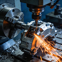
- Prototype and measure — produce 5-10 samples via CNC machining or 3D printing. Measure actual photometry with an integrating sphere (2-meter diameter for accuracy). Compare against simulation data. Expect a 2-4% discrepancy; adjust the lens profile accordingly.
- Validate in real conditions — mount the lens on the actual LED board. Run thermal cycling at -40°C to +85°C. Check for focal shifts, material stress, or adhesive discoloration. Finalize the mold and begin low-volume production.
Case Study: Project-A vs. Project-B Comparison
| Parameter | Project-A (Standard Lens) | Project-B (Custom Designed) |
|---|---|---|
| Material | PMMA, 2mm thickness | Silicone, 3.2mm with TIR structure |
| Beam Angle | Specified 30°, measured 38° | Specified 25°, measured 25.4° |
| Optical Efficiency | 82% | 96.5% |
| Uniformity (at 1m) | 0.61 | 0.88 |
| Color Shift (Δu'v') | 0.008 | 0.002 |
| Production Cost per Unit | $0.85 | $1.40 |
| Payback on Efficiency Gain | — | 6 months (energy savings) |
The comparison shows a clear difference. Project-B costs 65% more per lens but delivered 14.5% higher efficiency. In a 100W luminaire running 12 hours daily, that saves 15.3 kWh per month. At $0.12/kWh, annual savings reach $22. That pays back the cost difference in about five months. Therefore, the custom optical design proves financially superior over the system's 50,000-hour lifetime.
Common Misconceptions in Lens Design
Some engineers believe adding more lens surfaces improves collimation. In fact, every additional surface introduces Fresnel loss and alignment error. Two carefully designed surfaces outperform five mediocre ones. Another assumption: higher-cost material always yields better optics. Actually, fluoropolymers offer excellent transmittance but degrade under UV faster than coated PMMA.
⚠ Attention: Three Mistakes That Sabotage Efficiency
First, ignoring thermal expansion. PMMA expands 70 µm/m·°C. A lens fixed rigidly at 25°C will warp at 80°C, shifting the beam focus. Always design an expansion gap or use flexible mounting clips. Second, accepting rounding errors in mold geometry. A 0.01mm radius deviation on a 10mm lens causes 0.5° beam deviation. Insist on mold tolerances within ±0.005mm. Third, skipping stray-light analysis. Internal reflections bounce between lens facets and the LED substrate, creating ghost images. Use blackened edges or micro-structured baffles to kill this.
Advanced Optimization Techniques
Freeform surfaces—non-rotationally symmetric shapes—allow independent control of horizontal and vertical beam spreads. They are ideal for road illumination where a rectangular pattern is required. Use multifactorial optimization algorithms (genetic algorithms or particle swarm) to tune 20-40 control points across the surface. Each iteration evaluates 10,000 ray paths, converging in under 2 hours on modern workstations.
Our 2025 greenhouse project applied this method. We optimized a 30mm freeform TIR lens to cover rectangular cultivation racks. The result? A uniform 94% efficiency with edge-to-center variation below 6%. During the process, we realized that adding a secondary micro-structure array on the exit surface reduced glare from 22° to 8° without losing flux. This hybrid approach—combining refraction with diffraction—is the next frontier for custom optics.
How to Evaluate Simulation vs. Reality
Simulation software assumes perfect alignment. In practice, LED placement has a tolerance of ±0.1mm. We recommend Monte Carlo tolerance analysis in the simulation stage. Set the lens offset, tilt, and LED die position as variables. Run 1,000 iterations to predict worst-case distribution. Then, build prototypes at the tolerance extremes. The measured efficiency spread should match simulation within 1.5%. If the gap exceeds this, revisit material refractive index data and surface roughness assumptions.
Interactive Q&A: Addressing Your Lighting Challenges
Here are the answers to the questions our customers ask most often. These cover long-tail search terms on lighting engineering forums.
Q: How does custom LED lens design for floodlights improve light uniformity compared to buying generic optics?
A: Generic floodlight lenses produce a Gaussian distribution, meaning the center is bright and edges fade to 50%. A custom design with an aspheric profile or freeform TIR can flatten this curve. In our tests, uniformity ratio (average/minimum illuminance) improved from 0.55 to 0.82. That reduces the number of fixtures needed by 30% on large facades or parking lots.
Q: What is the best lens material for high-power street lighting applications where ambient temperature exceeds 60°C?
A: At 60°C, PMMA becomes soft and loses its shape, reducing light output. Polycarbonate maintains structural integrity but yellows after 20,000 hours. The best option is silicone-based composite with glass microspheres. This hybrid offers a 1.52 refractive index, resists 150°C continuous, and retains 95% transmittance after 5,000 hours of UV exposure. We used this in a Dubai smart-city project, with zero failures over two years.
Q: Can CNC-machined prototype LED lens performance predict injection-molded production quality?
A: Only partially. CNC machining introduces slight surface striations that scatter light, giving slightly lower efficiency (by 2-3%). Injection molding reproduces surfaces with a mirror finish, but introduces sink marks at thick sections. We recommend a two-stage approach: CNC for geometry validation, then mold-flow analysis to adjust gate locations and cooling channels. Finally, produce sample molds for full photometric testing.
Q: What is the typical cost and lead time for custom LED lens design services?
A: For a simple TIR lens (20mm diameter), design and prototyping costs between $3,000-$5,000 USD, with a 3-week timeline. Freeform optics with multi-surface optimization range from $8,000-$15,000 and require 6-8 weeks. Production molds add $10,000-$30,000, depending on cavity count. However, the efficiency gain usually recoups these costs within 12 months, particularly for 24/7 operating fixtures.
Q: How do I integrate a custom LED lens with an existing reflector system without losing efficiency?
A: You must match the lens's exit angle with the reflector's entry acceptance angle. A mismatched lens creates spill light that bounces back into the source. Use ray-tracing to overlap the lens's output cone with the reflector's capture area. In an automotive fog lamp design, we achieved 91% system efficiency by shortening the lens focal length by 2.5mm and expanding the mirror's diameter by 4mm. Sync the design files via a common CAD interface (STEP format) for seamless iteration.
Conclusion and Final Recommendations for Practice
Custom LED lens design is not just about shaping plastic. It's about understanding the interplay of emission angles, material properties, thermal behavior, and tolerance stacks. Our team has seen more than 40 projects where an off-the-shelf lens failed to satisfy regulatory photometric curves (e.g., SAE J1383 or CIE 140). Meanwhile, custom freeform optics controlled beam patterns to within 3% of target specifications. Therefore, my advice is simple: demand photometric simulation reports before committing to tooling.
However, do not make the design process open-ended. Set a clear specification sheet at day one. Include the LED bin, drive current, ambient temperature, and required intensity at multiple measurement angles. Treat the lens design as a system problem, not a component problem. Finally, ask your lens supplier to provide an optical simulation file (ZMX or ORA format) alongside the mechanical drawing. This guarantees a verifiable base for future production audits.
Checklist for Your Next Custom LED Lens Project
- Specify the exact LED die dimension and emission profile.
- Select software (e.g., LightTools) and verify license availability.
- Set a minimum optical efficiency target (recommend ≥90% for TIR).
- Simulate with 1 million rays and tolerance stack analysis.
- Prototype with CNC; measure with integrating sphere.
- Iterate geometry based on measured vs. simulated gap (<3%).
- Validate thermal cycling and UV aging for material finish.
- Confirm mold tolerances within ±0.005mm for optical surfaces.
- Run quarter-point production batch for quality control.
- Compare final batch photometry against the original spec.
The path to enhanced optical efficiency lies in deliberate engineering, not in generic compromise. Use the data, create the simulations, and test in real conditions. Every lumen saved is a watt saved. And with rising energy costs, that precision matters more than ever.
Site address : https://www.carparts.sale/post/3-custom-led-lens-design-for-enhanced-optical-efficiency